(In preparation, link will follow soon!)
Hello, Aircraft Mechanical Engineer!
Assume that you’re working for an aircraft manufacturer. You’re the mechanical engineer in charge of designing the structural elements of the aircraft.
You need to figure out how the following components mechanically look like in your aircraft:
- Fuselage (Skin + Frames + Bulkhead + Stringers)
- Wing
- Control Surfaces (Aileron, Elevator, Rudder)
- Hi-lift Surfaces (Slats, flaps)
… to a detail that you can tell your manufacturing partners what to make for you.
OK, that sounds interesting!
… So how exactly does that work?
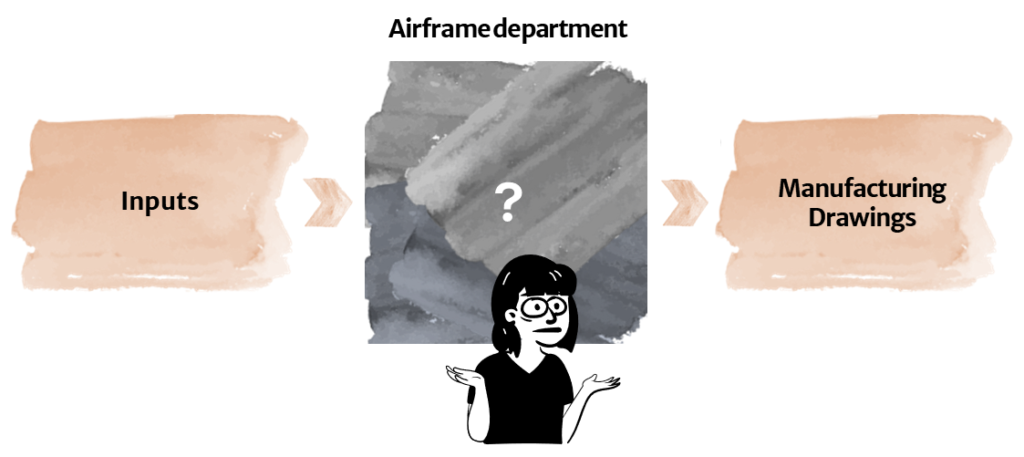
Unboxing the Blackbox
With many things to consider, engineering design work can sometimes feel like a blackbox where get lost in options without being able to see a clear path anymore.
Here we will break down the blackbox work of “design work” in the aircraft structures department into an extremely simplified, highly watered-down version of the process. First we aim to understand the flow, then we add more details to it.
With this first article of the series, we start by looking at the design of one of the control surfaces – Aileron.
Design Thoughtflow
Step by Step

(1) Prepare basic aileron shape.
By the time you’re at this level of design, the basic airfoil shape has probably already been defined, due to the need to have these determined at the preliminary sizing level. Therefore, get the following data from your preliminary sizing / aerodynamics engineers:
- Airfoil shape that was chosen
- Width of the aileron
- Length of the aileron

(2) Make decision on spar concept.
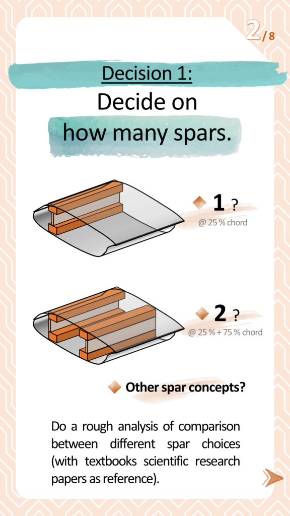
Decide on how many spars you will stick with, as well as which spar concept.
To extremely simplify the decision, choose between the two options:
- 1 spar (I-beam), @ 25% chord
- 2 spars (Two C-beams), @ 25% + 75% chord
This might turn out to be a more complex decision, involving multitudes of intertwined big impacts downstream. When feeling overwhelmed, start by choosing one of the easy options as baseline. Then see if any research brings up better alternatives, and weigh the difference in pros & cons.

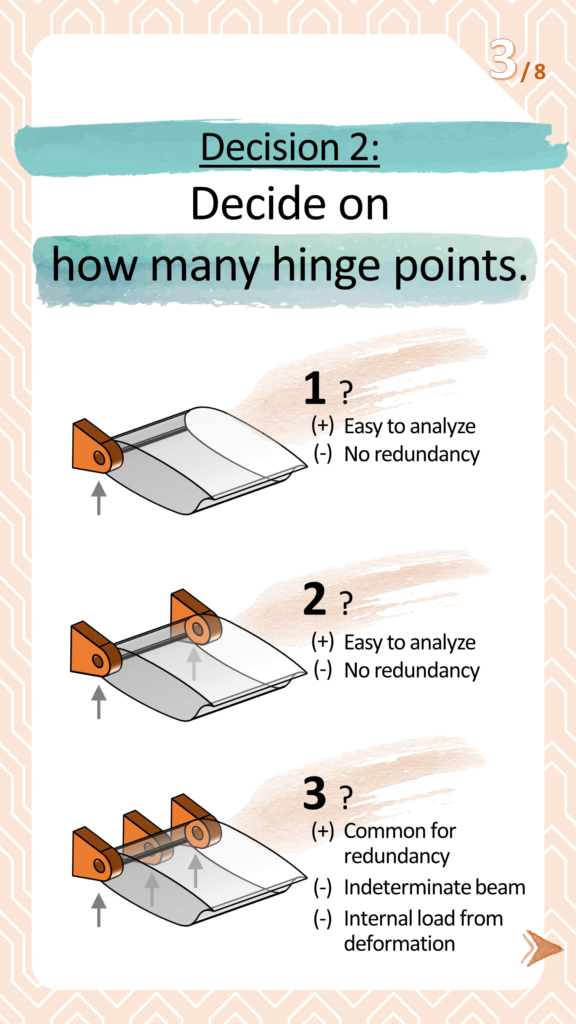
(3) Decide: Hinge point amount.
Decide on how many hinge points you would like to have.
- 1
This option is easy to calculate, but has no redundancy to structure. This means that if this hinge fails, you will lose this component.
If losing this one aileron leads to catastrophic failure of the aircraft, this option would not be ideal. - 2
This option is easy to calculate, but has not enough redundancy to structure. This means that if one hinge fails, you likely will lose this component. (Even though it has 2 hinges.)
If losing this one aileron leads to catastrophic failure of the aircraft, this option would not be ideal. - 3
This option provides enough redundancy and is a commonly selected option for important components. However, because the component hinge axis would be like an indeterminate beam (overconstrained), deformation would lead to internal loading of the component. The analysis of this component thus can become not so straightforward.

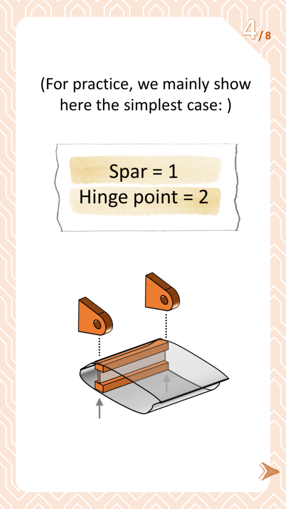
(4) Simplified Example.
For simplicity, here we will mainly show the thought-flow using the simplest case:
- Spar = 1
- Hinge point = 2

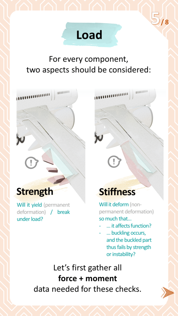
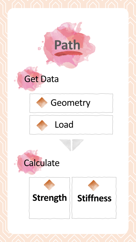
(5) Load – What to check?
Before we start load sizing, we need to know what we’re checking.
For every mechanical component, we always need to check these two traits:
- Strength
Is the part strong enough, that it doesn’t “break” under load? - Stiffness
Is the part stiff enough, that it doesn’t deform in a way that affects function or breaks?
Let’s gather all the force and moment data, to calculate these two aspects.


(6) Load Simplification
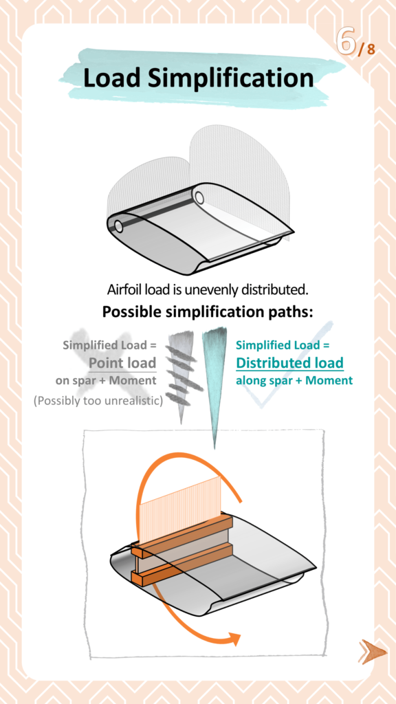
On an airfoil, the load is distribution is likely to be not uniform. How can we simplify this?
One simplification method could be to assume the overall airfoil load = Distributed force along spar + a rotational moment around its CG. The value of this distributed force could be the maximum value of your airfoil’s overall load profile, depending on the desired level of conservatism in calculation.
Then, assume all the bending force is sustained by the spar(s), and all torsion moment is sustained by the skin.
Generally important : Remain vigilant about assumptions.
Think about “what assumptions am I working under” and remain attentive on “whether other people’s assumptions apply to my case, and whether the previous assumptions are still true.”

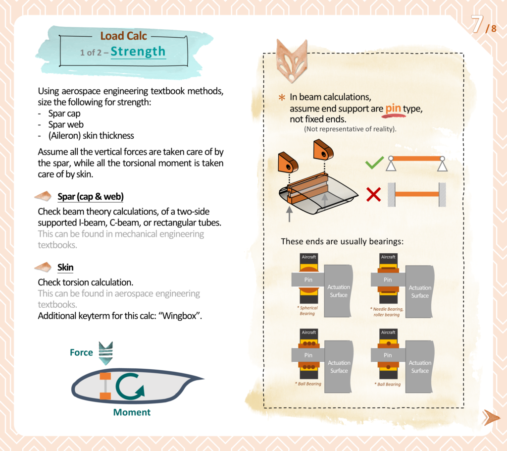
(7) Load Calculation (1 of 2) – Strength
This is probably the part with the most extensive textbook literature available. Try to check out aerospace design engineering and mechanical engineering textbooks, especially searching for the term “wingbox.”
Assume all the vertical forces are taken care of by the spar(s), while the skin takes all the shear coming from the torsional moment.
When calculating the spar(s) by using the beam theory, assume that the end support are “pin” types (Translation not possible, rotation possible), instead of fixed ends (Translation not possible, rotation not possible). This is because these hinge supports are usually bearings that allow for rotation when the component deforms. Even when using needle bearing or ball bearings where the allowable rotation might be small, it is still not realistic to simulate this as fixed end.

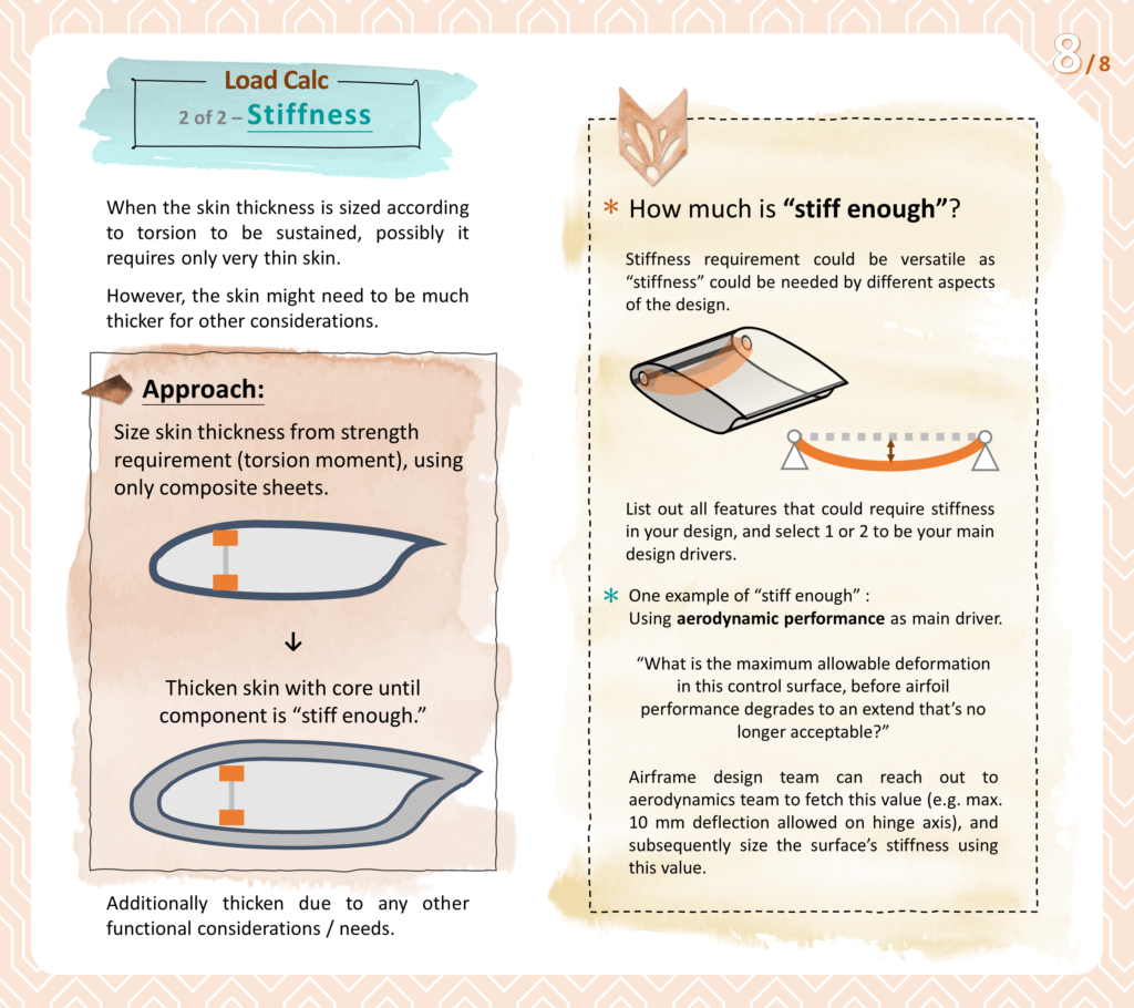
(8) Load Calculation (2 of 2) – Stiffness
When the skin thickness is sized according to torsion to be sustained, possibly it requires only very thin skin. However, the skin might need to be much thicker, for reasons such as:
- Staying stiff enough for aircraft (aerodynamic) performance
- Easier manufacturing
- Easier handling
- Buffer for repair (From e.g. workers accidentally dropping tool on part)
Therefore, first size the component using strength as mentioned in the previous step, and then thicken up the structure with core until component is “stiff enough”.
The criteria on when a component is “stiff enough” could require a bit of exploring, because stiffness is needed by multiple functional aspects. To start, list out all features that could require stiffness in your design, and select 1 or 2 to be your main design drivers.
An example could be to use aerodynamic performance as the main driver. When the component deforms, its aerodynamic performance degrades. Therefore, a way to gauge the required stiffness could be the maximum deformation allowable before the component’s aerodynamic performance degradation becomes unacceptable. By defining this max. deformation value with the aerodynamics team, you could have a more clear standpoint to design further.
📣 This article was made possible thanks to consultation with Sebastiaan Engelen, who is an experienced aircraft design engineer who took part in designing large-scale drones used for airborne wind energy for Ampyx Power, as well as review from Durk Steenhuizen, who is also an experienced engineer on aerospace mechanical design. Thank you all!
